Homemade CNC Machine
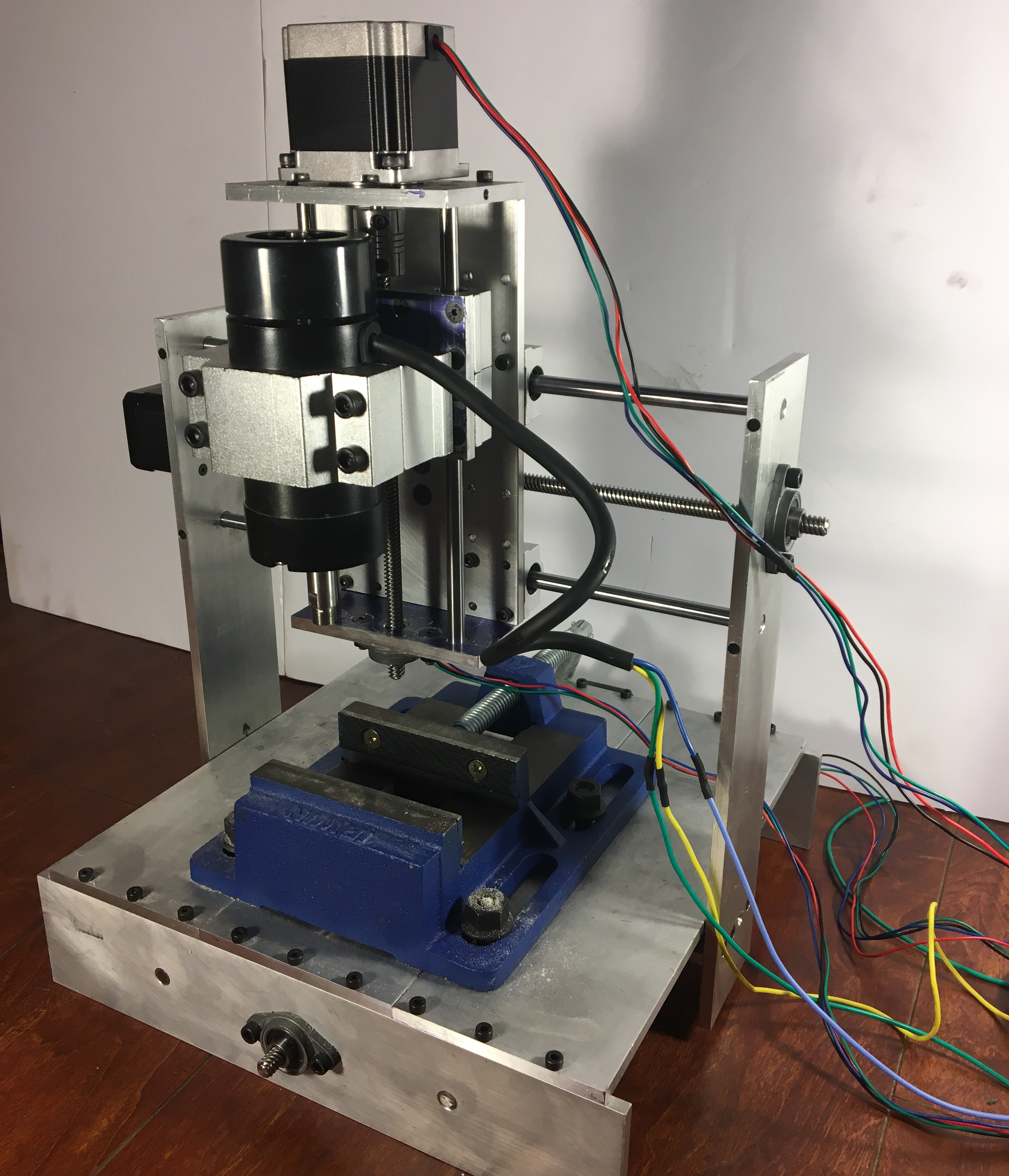
Pictured below is my homemade CNC machine. This was constructed to expedite drilling holes in homemade printed circuit boards for other hobby electronic projects. This was a project of passion which was developed over the course of a year during evenings and on weekends while working as a full-time engineer. Building it required all of my skills and learning new ones, including designing and machining mechanical parts, designing electronic circuits and of course lots of coding. It is as homemade as possible, with the majority of mechanical components being made myself on a G0704 milling machine and the design, while inspired by other DIY projects, is completely my own.
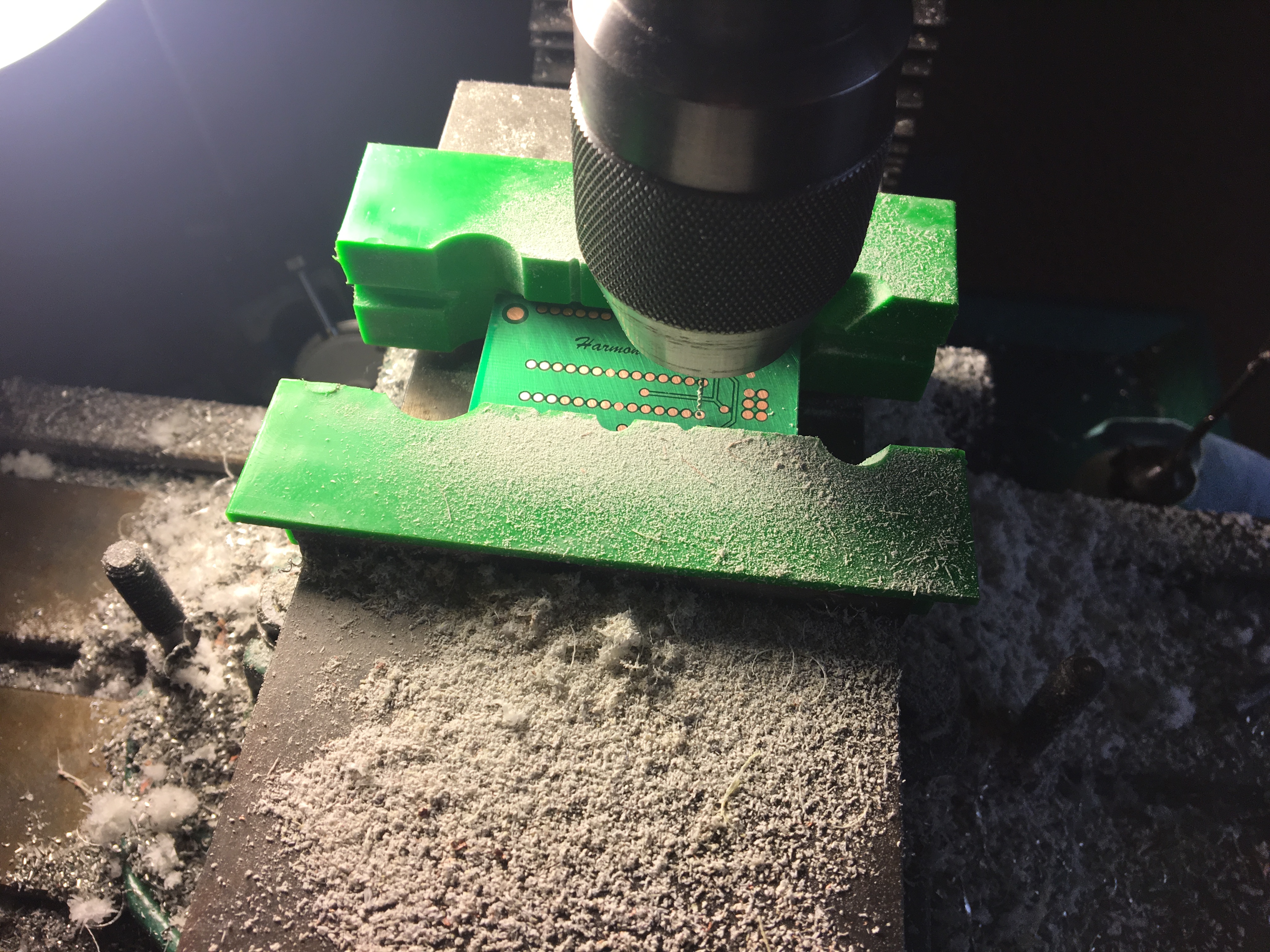
Below is a quick video of the CNC machine in action, drilling 0.7mm holes in a blank PCB.
System Block Diagram
The major parts of the system are shown in the diagram below. The basis of the system is an ATmega328P microcontroller which receives GCODE commands from a controlling PC via UART. The ATmega328P receives a location to move the CNC spindle, calculates a path, and commands the stepper motors to move along the X, Y, and/or Z axis.
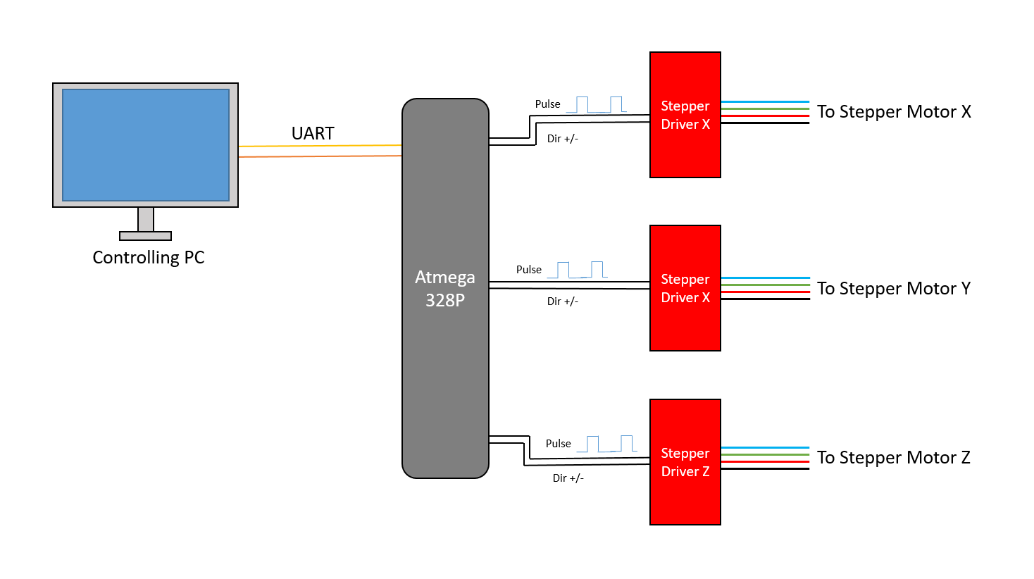
Each of the three stepper motors is driven by an EasyDriver board. This simplifies the control from the microcontroller point of view and reduces required pins as each step is commanded by a pulse from a single connection. Additionally, each driver has a connection for direction control and one for mode control (1/8 step vs full step).
Host PC Program
In order to send commands to the microcontroller, run scripts, display location, etc, I wrote a host PC program, or GCODE Console as I will refer to it from now on. It is written entirely in Python and using the wxWidgets library for the GUI. A screenshot of this program is shown below.
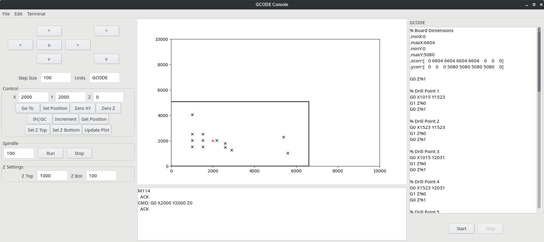
The program uses threading to continuously update the display on the main screen while also running scripts in the background.
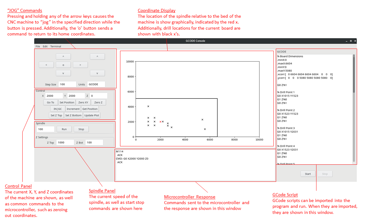
A rundown of the basic functional areas of the program are shown below.
ATmega328P Program
The Atmega328P needed the ability to translate the commands coming from the host PC into motion of the stepper motors. The source code for this program can be found here. A high level view of the program flow is shown in the UML diagram below. The Atmega328P program reads in commands through its UART hardware and compares them to a list of valid commands. If the command requests a diagonal line move or a curved move, the coordinates of the command are put through an algorithm which calculates the closest approximation of said line or curve using discrete steps. These steps are sent as pulses to stepper motor IC chips which redirect power from a 12V supply to drive individual lines of the stepper motor.
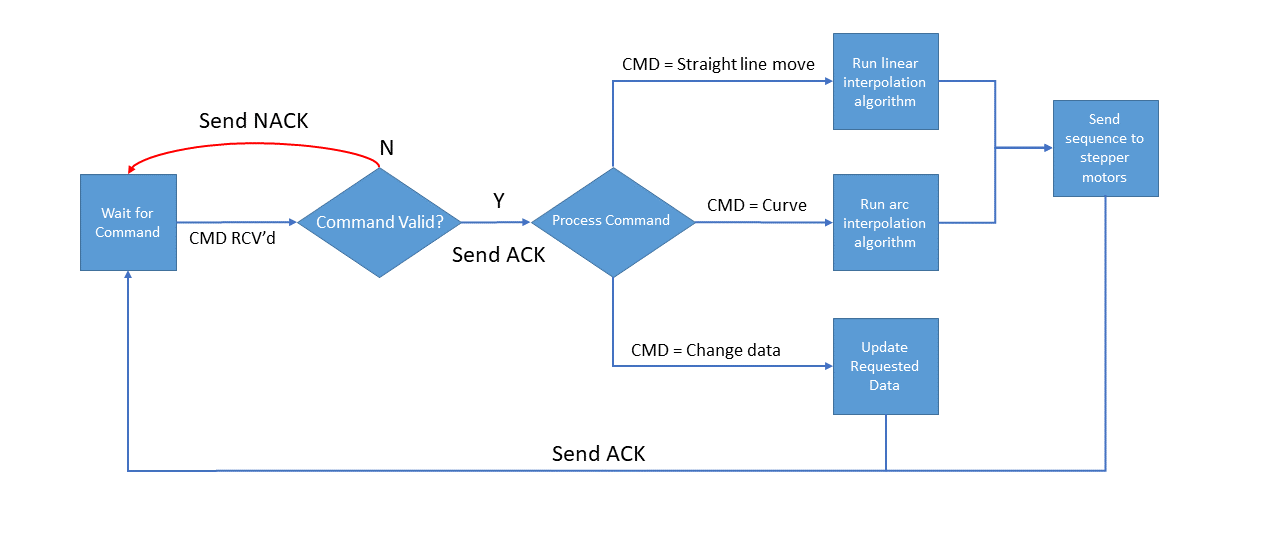
The algorithm for determining stepper pulses to approximate a diagonal line or curve was adapted from this paper, titled XY Interpolation Algorithms by Kenneth and Melvin Goldberg.
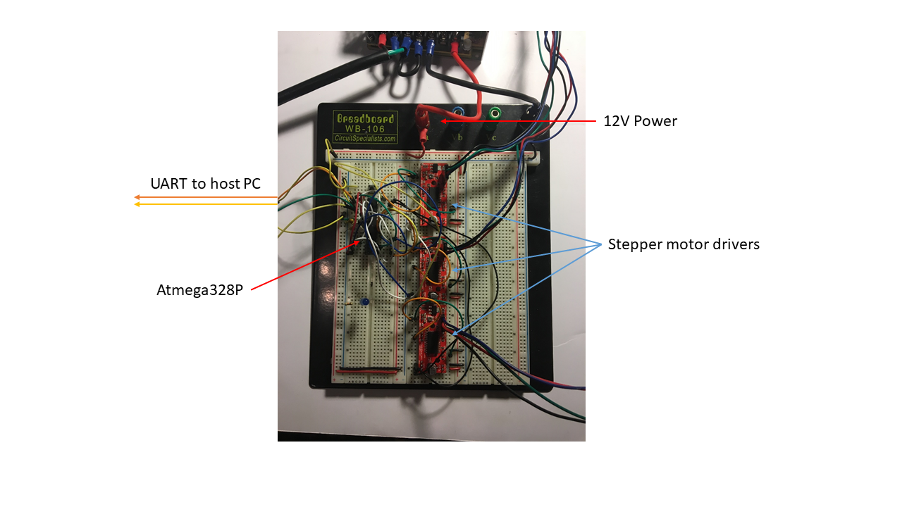
Breadboard
Currently, the circuit is still in breadboard form. I am currently working on a design in EAGLE to transfer it to something more permanent.
Mechanical and Electrical Parts
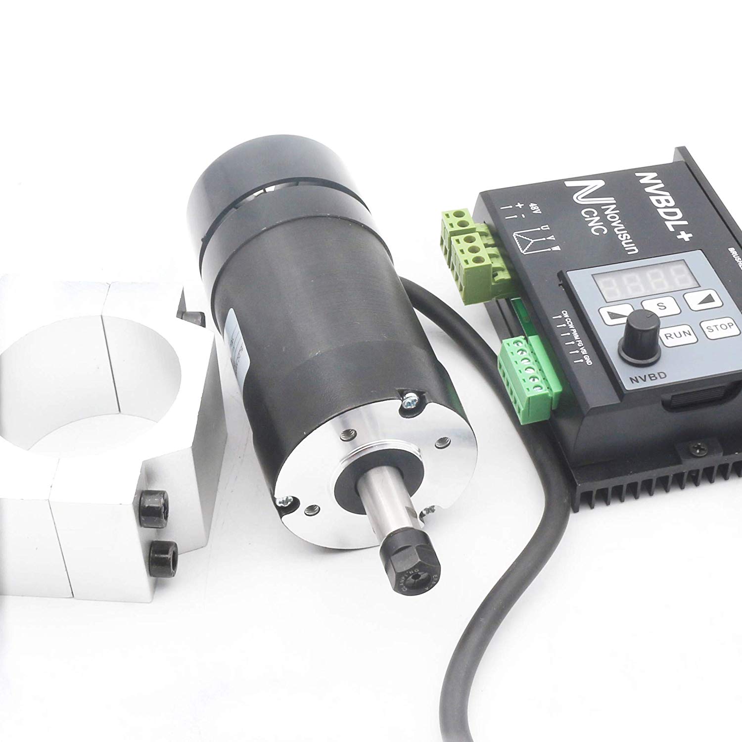
The spindle used in this project is 400W air cooled and was purchased from RATTMMOTOR here. It uses a separate control board to set its speed and runs off of this 48V power supply.
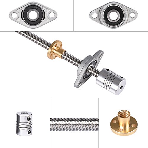
The lead screw and associated hardware used in this project for axes control are common to most 3D printers.
The remaining parts were machined from 1/4" thick 6061 aluminum rectangular extrusions.
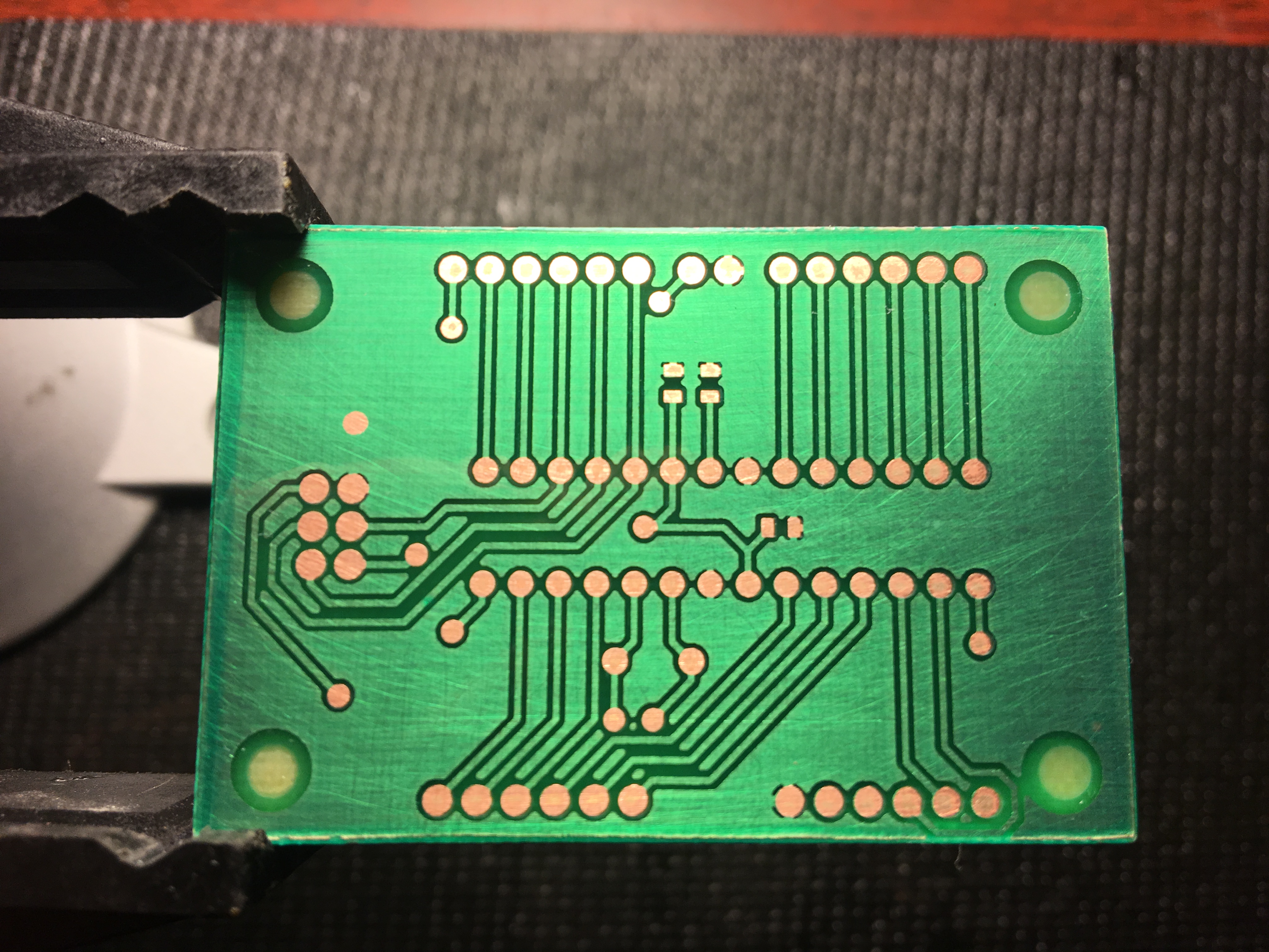
Why bother?
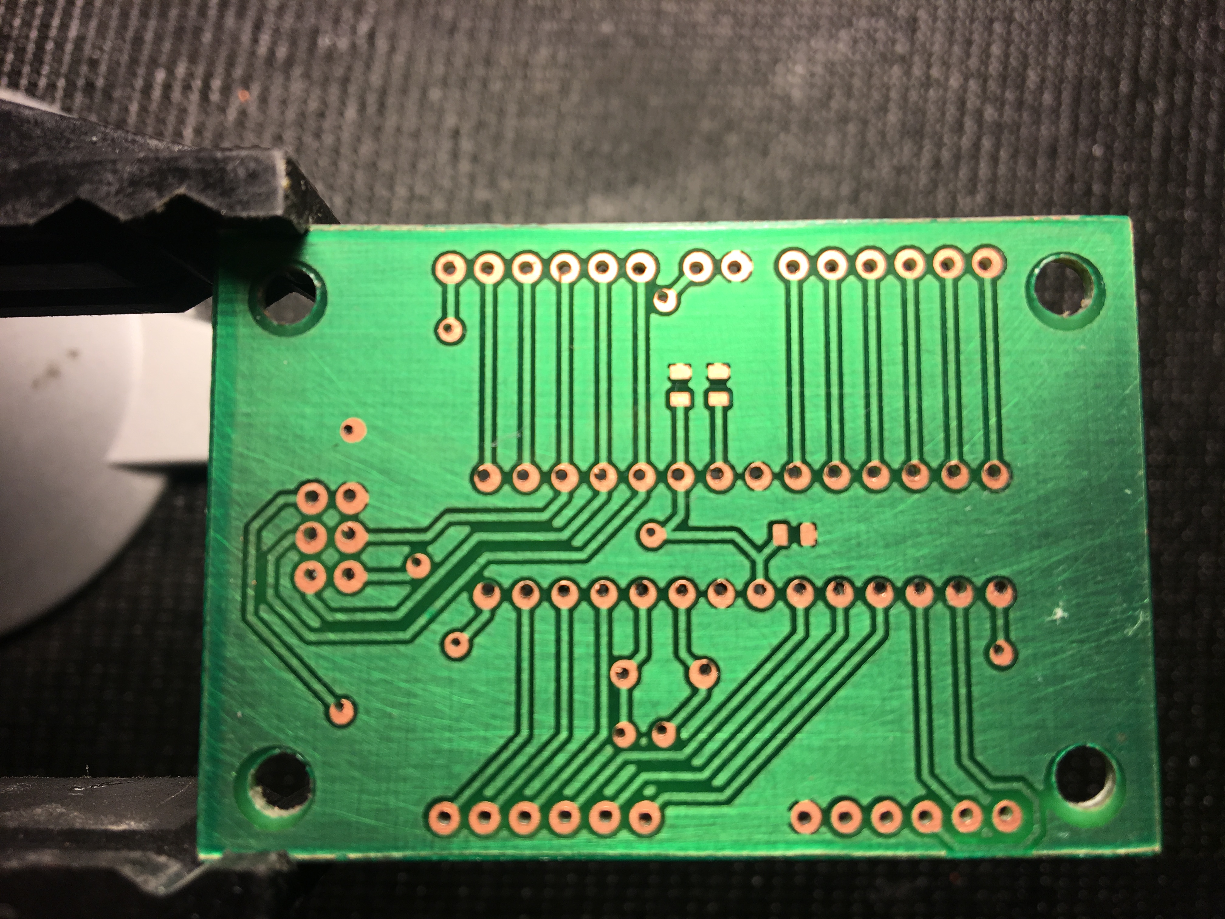
This project has been an effort to simplify making PCBs for other projects. Until now I have been hand machining every hole in the boards I make, which can be extremely time consuming. For example the board below, an ATmega328P breakout I designed, has over 50 holes!