AVR Atmega328P SPI
Serial Peripheral Interface (SPI) is a very useful data transfer protocol for microcontrollers. It is the method used by programming devices like the usbtiny to transfer programs to AVR microcontrollers and is a way to interface with SD cards, among other things.
Unlike UART, SPI is synchronous, meaning data transfers are synchronized to a shared clock signal between the two communicating devices. This significantly simplifies the implementation at a hardware level, requiring little more than shift registers, and also means that the baud rate between devices does not have to be agreed on beforehand.
In addition, SPI requires one device to operate as a master, and other devices to act as slaves. The master controls all interaction on the SPI bus, while the slaves only send or receive data when instructed to do so by the master. The master controls each slave through a line called the slave select (SS), which it will drive low to indicate to a slave that it is required to receive or transmit. A general layout for this is shown below:
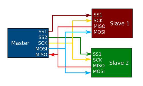
Note that SPI is advantageous in that all devices can share the same bus and there is no worry about stepping on each others communications. One drawback, however, is that the master must have a dedicated pin for each slave on the bus, which can be impractical for large numbers of devices.
Initializing SPI as Master
Here we will look at initializing SPI with the ATmega328P as master. We will assume that we have one device and are using PINB2 as chip select.
#define SPI_DDR DDRB
#define CS      PINB2
#define MOSI    PINB3
#define MISO    PINB4
#define SCK     PINB5

void SPI_init()
{
    // set CS, MOSI and SCK to output
    SPI_DDR |= (1 << CS) | (1 << MOSI) | (1 << SCK);

    // enable SPI, set as master, and clock to fosc/128
    SPCR = (1 << SPE) | (1 << MSTR) | (1 << SPR1) | (1 << SPR0);
}
The MOSI, MIS0, and Clock lines for the ATmega328P are PINB3, PINB4, and PINB5. Here we use define statements to refer to them by their function, rather than pin name. Since we are operating as master, CS, MOSI, and SCK need to be set as output. MISO is an input, which is set by default.
    // set CS, MOSI and SCK to output
    SPI_DDR |= (1 << CS) | (1 << MOSI) | (1 << SCK);
Next, we need to enable SPI in the SPI control register. We do this by writing a 1 to SPCR. We additionally specify that we are operating as master by writing 1 to MSTR. Finally, we need to set the clock rate. By default, it is set to Fosc/4. However, this may be too fast for certain devices. If you are not sure what the maximum clock rate of the device you are interfacing is, you should set the clock to the slowest rate possible. Here we do that by writing 1 to SPR1 and SPR0, which gives a clock of Fosc/128.
    // enable SPI, set as master, and clock to fosc/128
    SPCR = (1 << SPE) | (1 << MSTR) | (1 << SPR1) | (1 << SPR0);
Transmitting
Transmitting a byte as the SPI master is extremely simple. Here is a function that will do that:
void SPI_masterTransmitByte(uint8_t data)
{
    // load data into register
    SPDR = data;

    // Wait for transmission complete
    while(!(SPSR & (1 << SPIF)));
}
First we load the data that we need to transmit into the SPI data register, SPDR
    // load data into register
    SPDR = data;
Next, we poll the SPI Status Register, SPSR, waiting for the SPIF flag to clear.
    // Wait for transmission complete
    while(!(SPSR & (1 << SPIF)));
It is important to note that when transmitting to a device over SPI, the Slave Select line for the device you are transmitting to must be driven low before the data is sent. For example, using this function in context might look like
    // drive slave select low
    SPI_DDR &= ~(1 << SS);

    // transmit byte to slave
    SPI_masterTransmit(0x55);

    // return slave select to high
    SPI_DDR |= (1 << SS);
Receiving
Receiving data over SPI is very similar to transmitting.
uint8_t SPI_masterReceive()
{
    // transmit dummy byte
    SPDR = 0xFF;

    // Wait for reception complete
    while(!(SPSR & (1 << SPIF)));

    // return Data Register
    return SPDR;
}
You will notice that our function is almost identical to transmit. The main difference is that we always transmit 0xFF and return the SPI data register when we are done. 0xFF is transmitted since we need to generate a clock for the slave to transmit data back to us. We simply transmit 0xFF as a dummy byte to generate this clock signal.
An alternative to this is to combine these functions. You could, for example, write the function such that it always takes an input byte to transmit and always returns the SPI data register. For example:
uint8_t SPI_masterTxRx(uint8_t data)
{
    // transmit data
    SPDR = data;

    // Wait for reception complete
    while(!(SPSR & (1 << SPIF)));

    // return Data Register
    return SPDR;
}
Using this code, a transmit receive sequence would look like:
    // drive slave select low
    SPI_DDR &= ~(1 << SS);

    // transmit byte to slave (and ignore response)
    SPI_masterTransmit(0x55);

    // receive byte from slave
    uint8_t ret = SPI_masterTxRx(0xFF);

    // return slave select to high
    SPI_DDR |= (1 << SS);