ATmega328P DIP Breakout Board
As many of my projects involve ATmega328P boards, I decided to try my hand at making my own Arduino style breakout board. This board provides headers for an ISP connection, a 16MHz oscillator, breakout for all I/O pins, and a UART header.
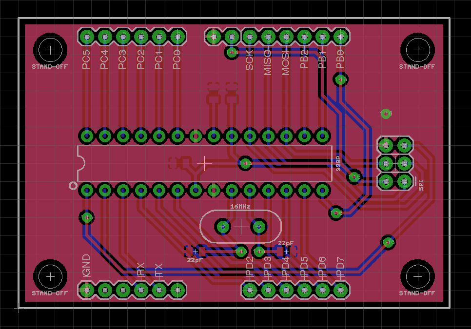
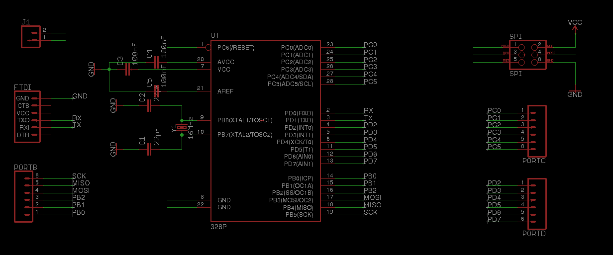
Below is the design I created in Eagle. Download the source files here. (Note: You will need to install the Sparkfun Parts library to view properly.)
Board
Schematic
Building
All of my boards are completely homemade. Here is an overview of the process used to creat them.
To begin with, I take a blank double sided copper board, like the one shown below.
The board is then scrubbed with rubbing alcohol and laminated with a UV sensitive film.
A negative image of the copper traces is printed out on overhead transparency for each side. To make sure no UV light bleeds through, each one is printed twice and overlaid.
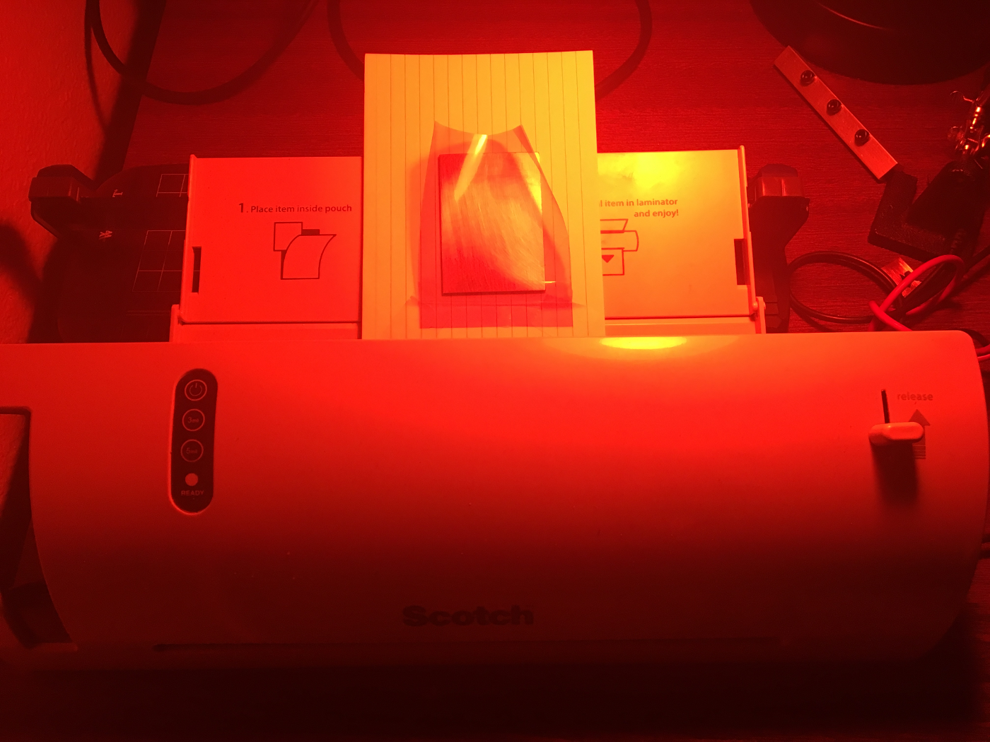
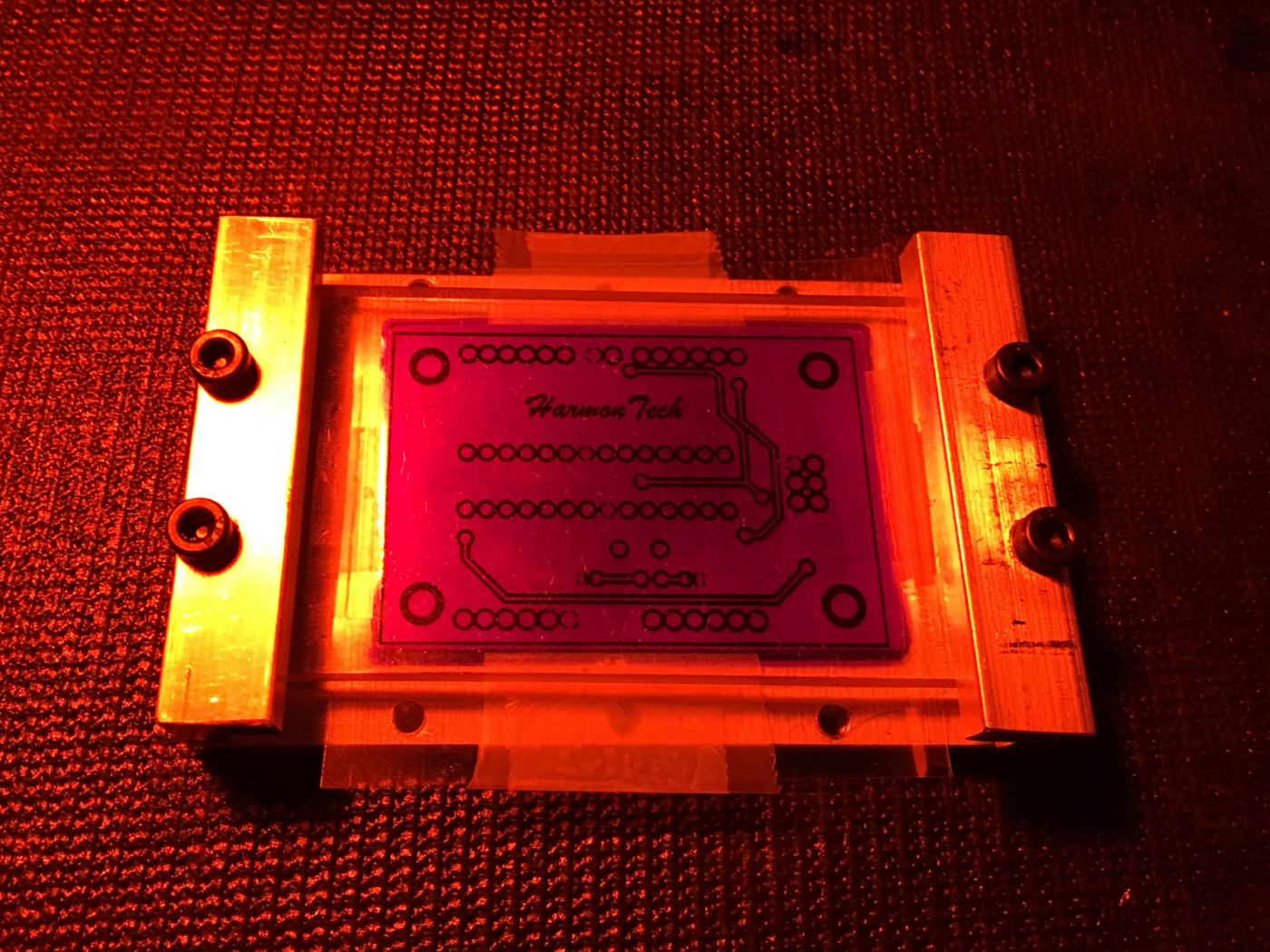
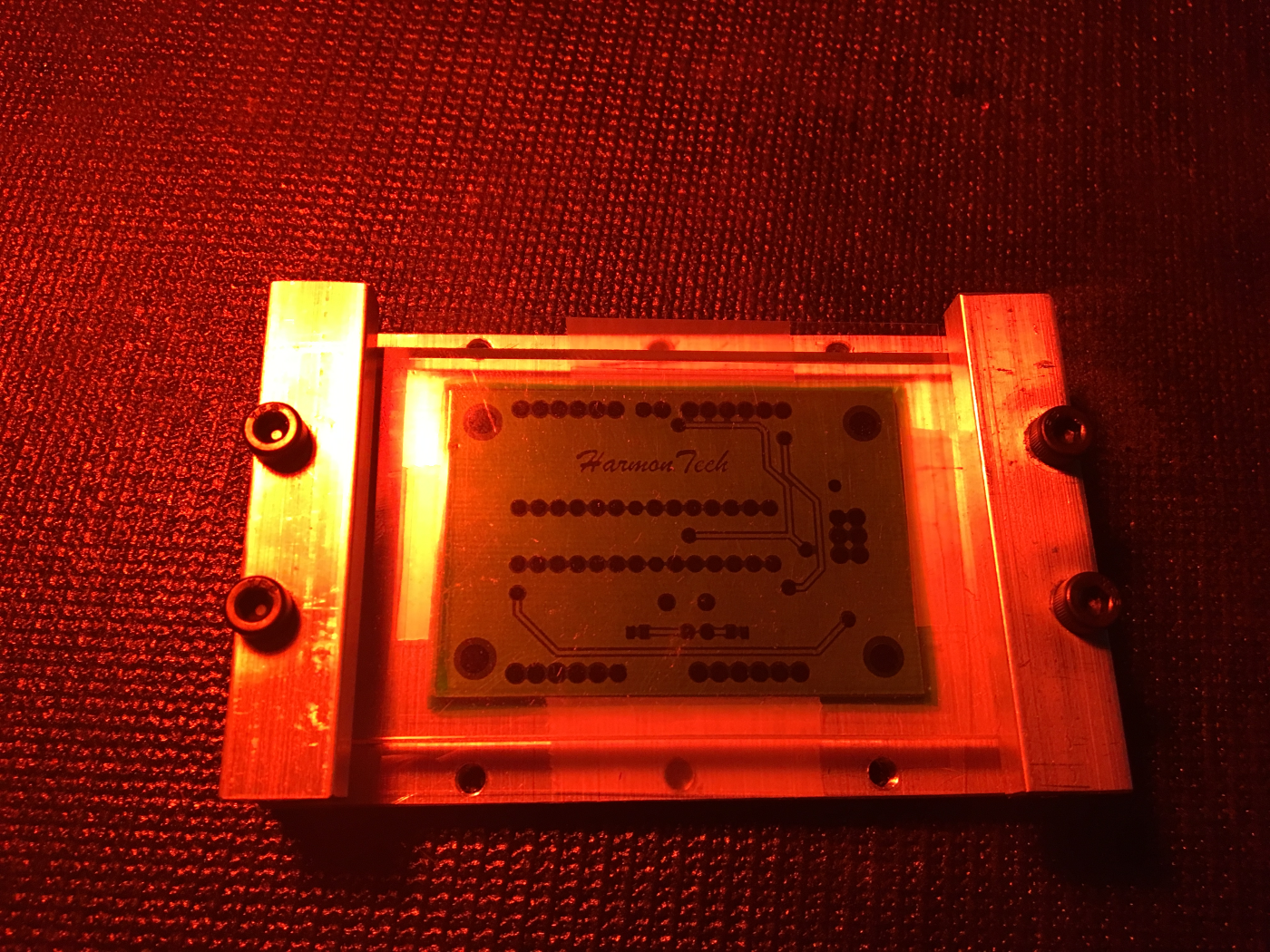
The transparency is aligned to the top of the laminated board and then placed in a jig. The jig has an acryllic plate which firmly presses the transparency flat on the board and ensures as little light as possible bleeds through the sides of the traces.
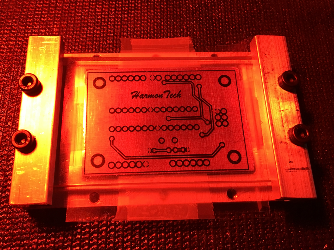
The board is then exposed to UV light for 30 seconds on each side, which cures the UV sensitive film in the exposed areas.
The board is then dipped in photodeveloper which dissolves the photosensitive layer in the places where it has not been exposed to UV.
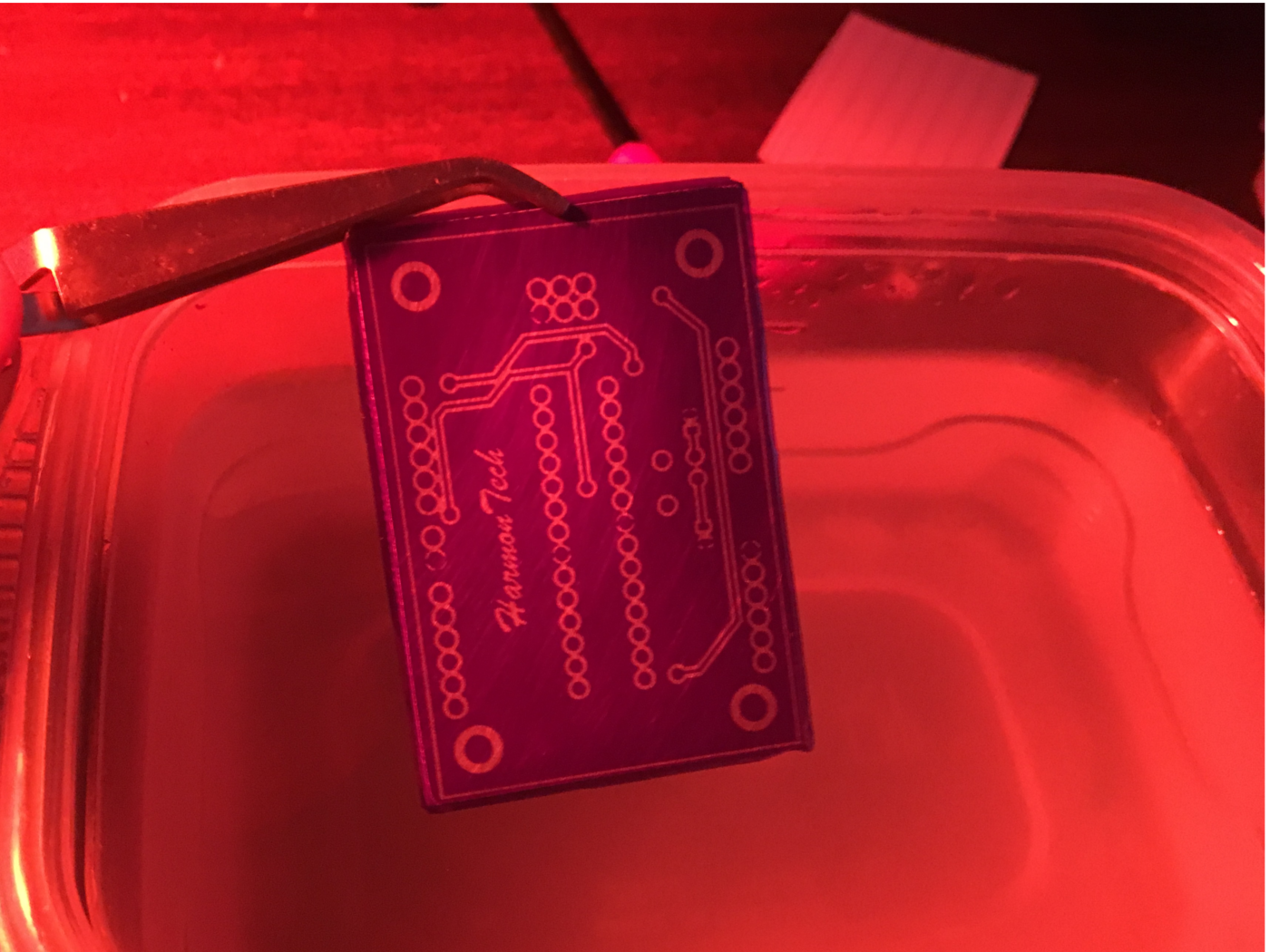
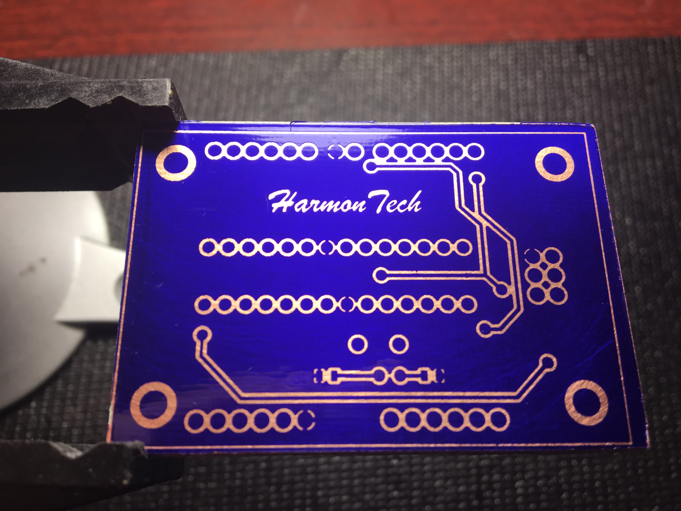
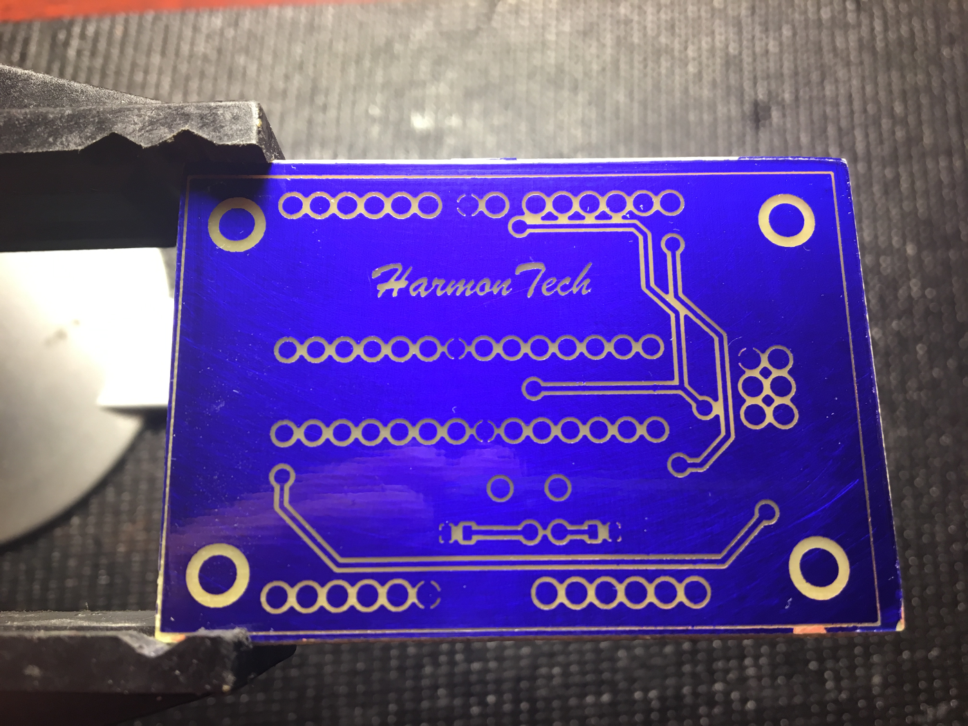
After gently brushing off the dissolved photoresist and cleaning the board, here is what it looks like.
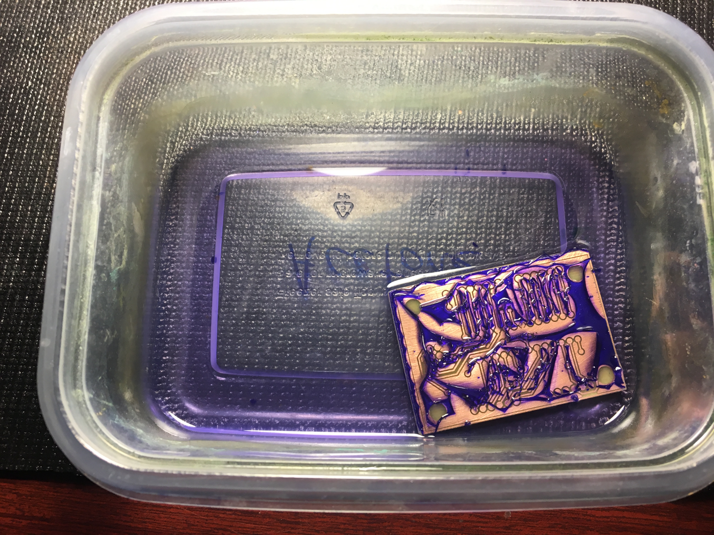
Next, the board is dipped in Ferric Chloride which etches away exposed copper.
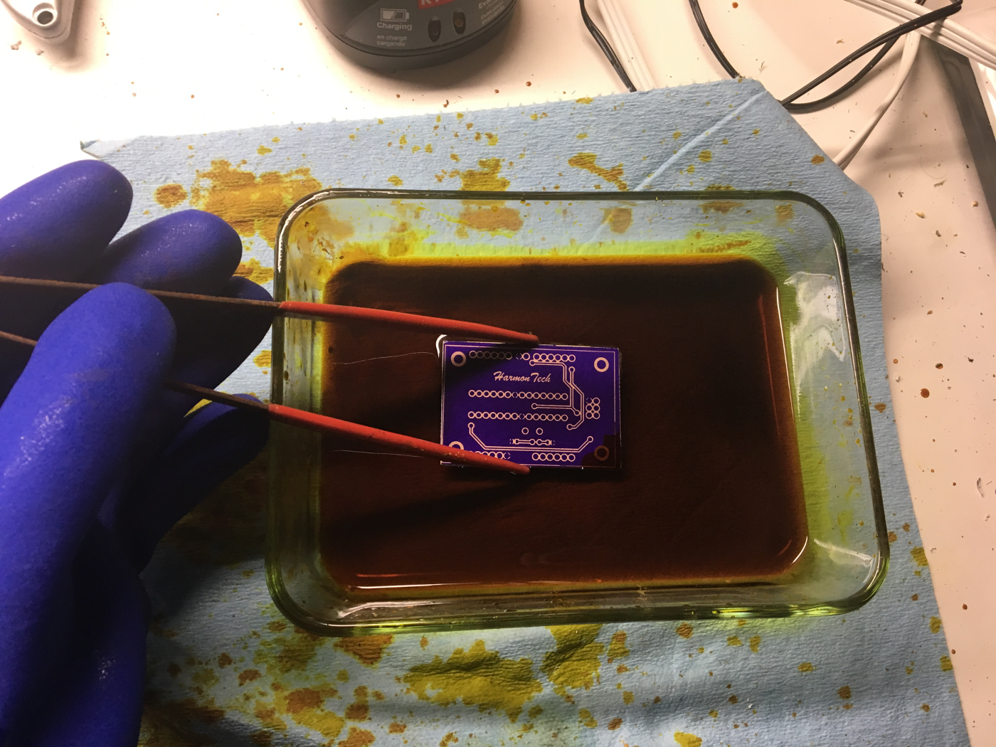
Here is the board after the etching is finished.
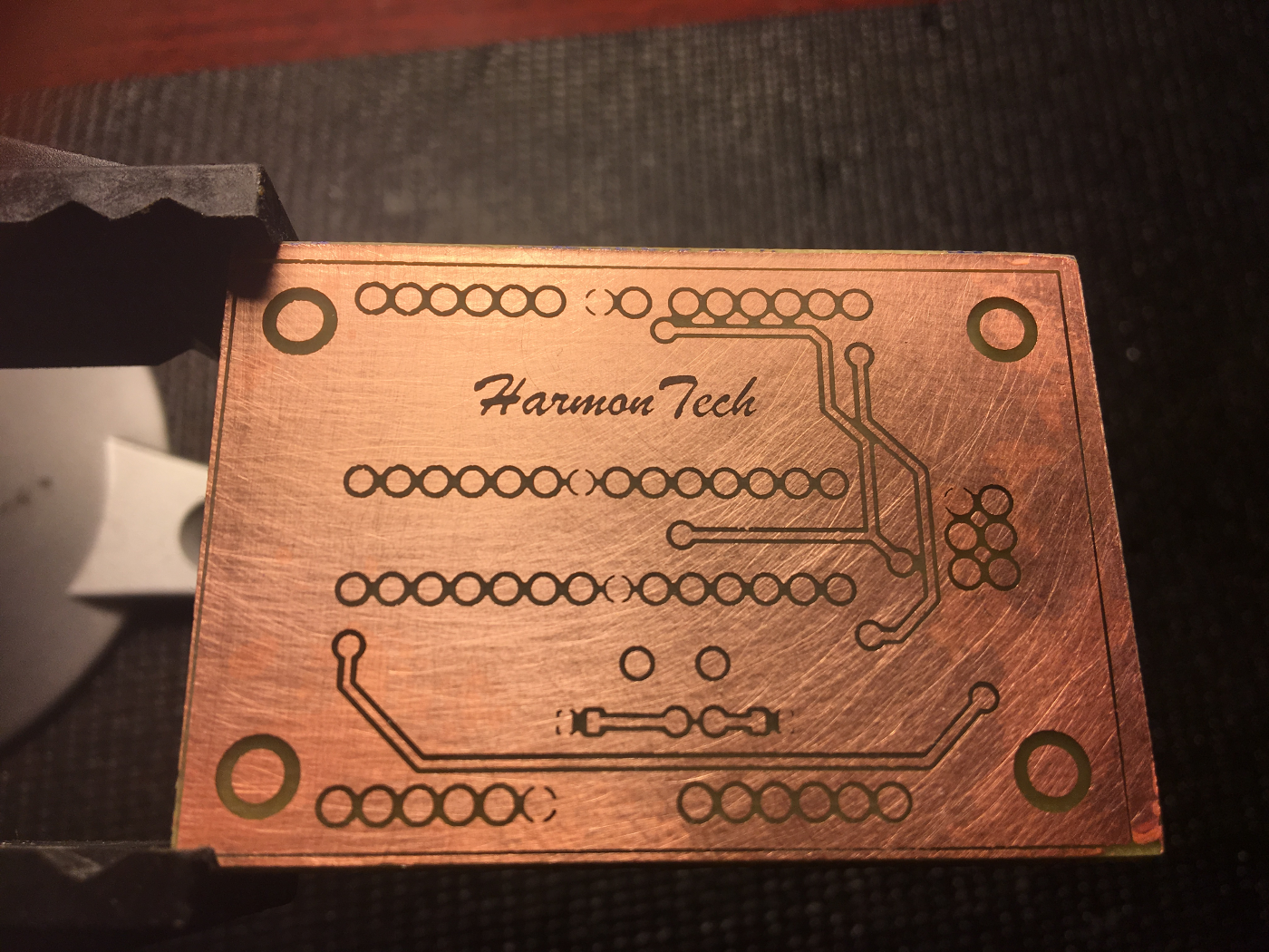
Dipping the board in acetone quickly removes the UV mask.
Here you can see the negative image has been etched away leaving the desired circuit on the board.
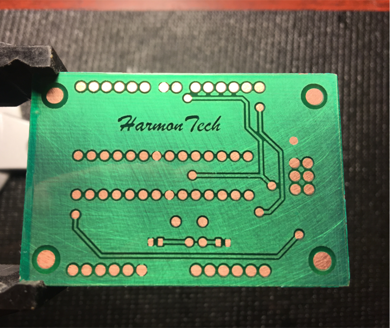
Now, a green UV mask is laminated on the board. Again, an overhead transparency is used to control what is exposed to the light. This time, only the places where parts will be soldered is covered.
After exposing to UV, the board is dipped in photodeveloper to dissolve the unexposed areas. Here is how it looks now.
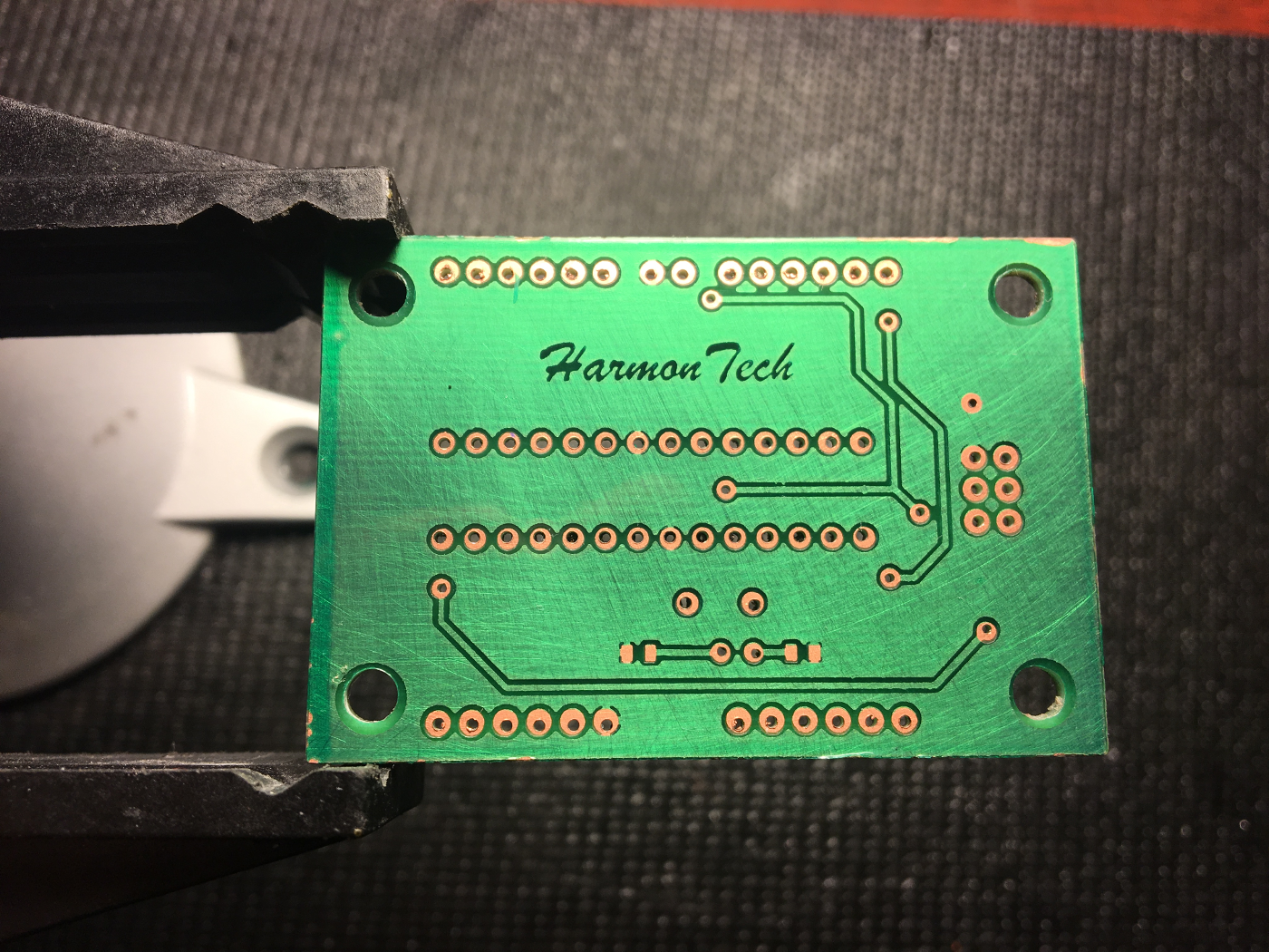
Now, the board is (tediously) drilled.
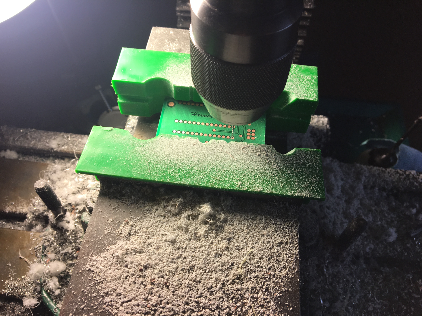
Here it is after drilling. Not perfect and took quite some time! (Note: this was the impetus for my CNC project here)
Finished Product
Finally, after soldering all components, here is the finished product.
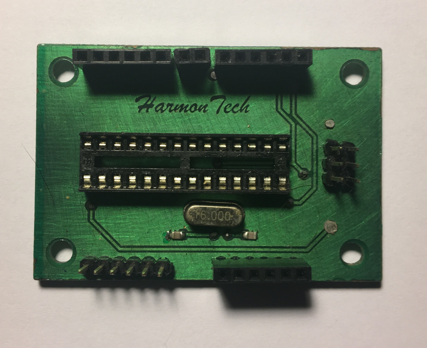
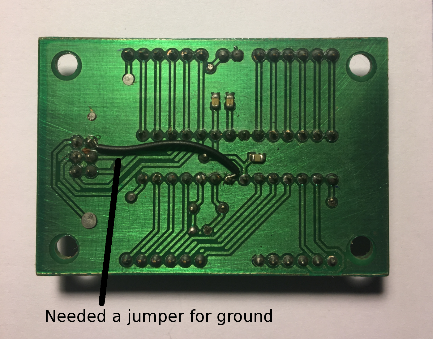
Unfortunately, I missed a connection to ground in my design, but it was fixed with a jumper between the ISP ground pin and the ATmega328P ground pin.
Other than that hiccup, the board turned out very well and functions as expected. My usbtiny programmer can communicate with the microcontroller when connected to the ISP headers, UART works, and timing is correct with the external oscillator. This was a challenging and time consuming board to build but definitely worth it.